


Jaideep Saraswat, Nikhil Mall
The sales of Electric Vehicles (EVs) are experiencing substantial growth while the era of Internal Combustion Engine (ICE) vehicles is nearing its end. Globally, it is projected that one out of every five car sales in 2023 will be an EV. Yearly estimates for EV sales continue to be adjusted upward as a result of the optimistic sales outlook, driven by factors such as decreasing battery costs, increased consumer awareness, and other contributing factors. However, as sales continue to rise, discussions about safety, particularly in the context of High Voltage (HV) EVs, where electrical hazards can be a concern, also come to the forefront. The objective of this article is to offer a brief overview of the various systems and mechanisms within an EV that are designed to guarantee the safety of both passengers and service technicians.
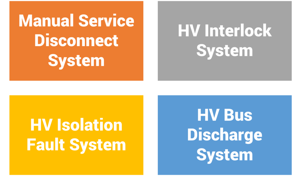
First things first, not all EVs fall into the HV category. According to ISO 6469-3, EVs classified as ‘High Voltage EVs’ are those belonging to voltage class ‘B,’ which includes vehicles with a DC voltage ranging from 60 V to 1500 V or an AC voltage ranging from 30 V to 1000 V. HV systems are preferred because they require a smaller cross-sectional area of copper to transmit the same power, resulting in decreased ohmic losses attributed to reduced current flow. This preference primarily applies to vehicles categorised as M, N, and O, including cars, mini-trucks, trucks, trailers, buses, and more. These specific EVs have the potential to pose electrical hazards if the voltage difference between their live components exceeds 25 V AC or 60 V DC, and if the short-circuit current reaches approximately 3 mA AC or 12 mA DC, or if the energy levels surpass 350 mJ. However, it’s important to note that EVs are equipped with various safety systems as depicted in Figure 1.
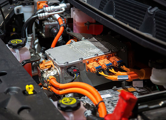
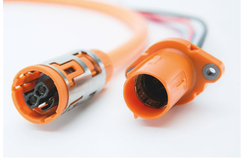
Before delving into the detailed examination of these systems, let us understand the essential aspects that contribute to maintaining safety in EVs. Firstly, it is mandatory for all wiring in EVs falling under voltage class B to be colored orange, serving as a clear visual identifier. However, it’s worth noting that the connectors, both male and female, are not specifically required to be orange themselves. Their classification within voltage class B can be discerned by examining the associated harness, as illustrated in Figure 2.
Secondly, safety measures and requirements to protect against electric shock are stipulated in accordance with ISO 6469-3. These measures encompass both fundamental protections against direct contact with live components and safeguards for scenarios involving a single failure. To prevent direct contact, protective barriers and enclosures with a minimum of IP 2X or IP XXB level of protection are employed.
Furthermore, in cases of single failure conditions, the exposed conductive parts of electric equipment classified under voltage class B must be interconnected with the electric chassis to ensure potential equalisation. Regarding isolation resistance requirements, the minimum acceptable value is set at 100 ohms per volt for DC circuits and at least 500 ohms per volt for AC circuits, with reference to the maximum operating voltage.
Thirdly, it is crucial to highlight the presence of a Ground Fault Circuit Interrupter (GFCI) or Residual Current Device (RCD) in EVs as seen in Figure 3. These are specialized circuit breakers designed to automatically cut off electrical power in the event of detecting an imbalance between outgoing and incoming currents. These devices can trigger their operation when they detect even a 0.005 A imbalance. This pivotal function serves as a protective measure, effectively preventing electric shocks resulting from occurrences such as short circuits, insulation failure, or equipment malfunctions.

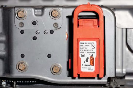
- Manual Service Disconnect System– The primary objective of a manual disconnect is to internally break the circuit within the battery pack. This action is a critical safety measure, particularly in scenarios where the HV contactors become stuck or inadvertently connect due to a collision. When the manual service disconnect system is activated, it results in a complete absence of voltage across the battery terminals. Various types of disconnect systems are available, including rotary, rotating lever with or without a bail, On/Off switch, and others. These disconnect devices are USCAR-2, USCAR-37 and IEC 60529 certified.
- HV Interlock System– This system functions to deactivate the HV system whenever an HV connector is disconnected. It accomplishes this by monitoring the loop current within components such as the traction inverter, DC-DC converter, and On-board charger. If an error is detected, the fail-safe mode is activated. This mode initiates a gradual discharge of the HV equipment and progressively reduces traction until the vehicle comes to a complete stop. It also triggers a Diagnostic Trouble Code (DTC), resulting in the illumination of the Malfunction Indicator Lamp (MIL) lamp on the dashboard, prompting the driver to visit a nearby service station. There are two versions of this system: Serial and Local/Grounded. The latter is advantageous in identifying the exact fault location but may incur higher deployment costs for each of the HV equipment.
- HV Isolation Fault Detection System– The HV Isolation system is in place to guarantee the maintenance of a safe resistance barrier, which effectively eliminates or reduces the possibility of an HV current pathway between HV components and the vehicle’s chassis ground. This system continuously monitors the vehicle’s chassis for any leakage of HV current, with the primary objective of ensuring the safety of both occupants and service personnel. In the event of detecting an isolation loss, it triggers the activation of the fail-safe mode, ultimately resulting in a loss of traction. It’s important to note that OEMs are obligated to report instances of isolation faults in compliance with the Federal Motor Vehicle Safety Standard (FMVSS 305).
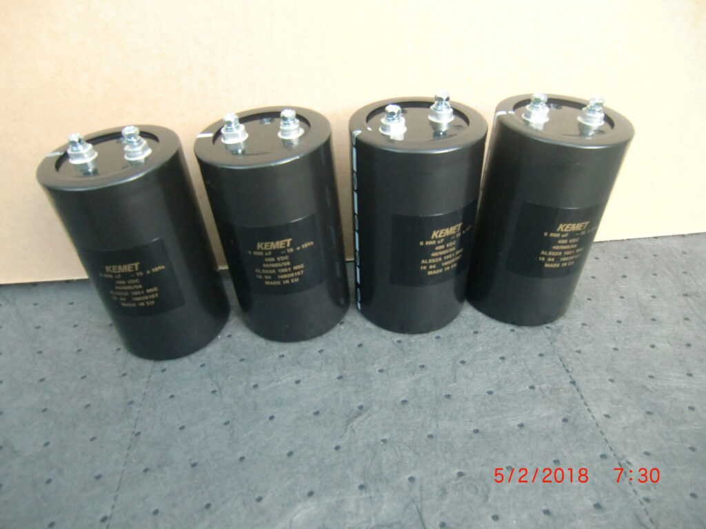
- HV Bus Discharge System– This system comes into play in various scenarios, such as during power-off, following a collision that compromises the HV system, during vehicle servicing, or when someone inadvertently comes into contact with the HV system. Its primary goal is to discharge the bus capacitors located near the traction inverter. Typically, there are two types of bus discharge systems: Active and Passive. The Active system consists of components like an Integrated Circuit (IC), resistors, and transistors, with a response time of approximately 250 milliseconds. This active circuit is commonly situated within the traction inverter, although it’s important to note that not all EVs incorporate active discharge circuits. Conversely, the passive discharge circuit is a more cost-effective solution, involving discrete resistors directly connected across the capacitors. However, in this setup, the discharge process takes longer, usually spanning from 3 to 5 minutes.
To sum up, the incorporation of these devices and systems guarantees the electrical safety of EVs, eliminating any potential hazards for everyone. Rest assured that EVs are electrically secure, so there’s no reason for this concern to impact your future vehicle purchases.
Image Source:
Figure 3: https://electrical-engineering-portal.com/ground-fault-circuit-interrupter-gfci
Figure 4: https://i.pinimg.com/736x/23/5a/ab/235aabcbb1a1a73df6a55a0ef148fb6b.jpg
Figure 5: https://www.guchen-eac.com/who/news/high-voltage-interlock-loop.html